GETTING STARTED WITH AHDL
A 12-Step Program by James P. Mabry
This is a very simple tutorial intended to illustrate how to start the AHDL tool in cadence, how to auto-generate module headers, and how to compile AHDL code. To access the online reference from the Cadence tool, do the following:
- From the CIW, click HELP->OpenBook Main Menu. A pop-up Main Menu will appear.
- From the Main Menu, click Analog/Mixed-Signal Simulation. Another pop-up menu will appear.
- From the Artist Menu, click Spectre.
- Click SpectreHDL Reference.
Start Tutorial Here.
- Create a symbol for a differential input, single output amplifier.
- From the symbol editor, click Design->Create Cellview->From Cellview.... The following pop-up window will appear.

- Click
on the Tool / Data Type button.
Select SpectreHDL – Editor from the available choices.
- Click
on OK to open the AHDL tool. A
pop-up window will appear with some header-type information at the
top. A sample header file is shown
below.
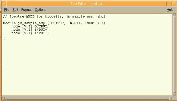
Note that there is no “port type” information in the
AHDL file. Unlike VHDL, there is no way
for the AHDL compiler to know whether a port is of type in, out, or inout. AHDL operates in a totally different way,
but in a way that better simulates the real phenomena in circuits. The node in AHDL is synonymous to the signal
in VHDL. However, in AHDL, nodes have
two values associated with them, Value and Flow. For our purposes, we will use (and the tool assumes that we will
use) Voltage (V) and Current (I), although that need not be the case.
- Close the file. A pop-up window will appear regarding saved changes.
- Choose YES to save. Another pop-up window will appear regarding Parser Error/Warnings.
- Choose YES to re-edit the file. The AHDL file will reappear, along with a list of Parser Error/Warnings.
Note that the software tool compiled the file as soon as you closed
it. Note further that the software that
generated the header code did so INCORRECTLY.
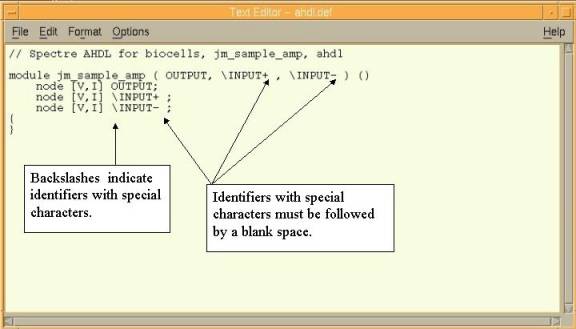
The AHDL parser is not able to determine whether the text input+ is
really one identifier called “input+”, or whether the text refers to a
identifier called “input” and the operation “+”. To clarify the situation, whenever special characters are used
within an identifier, the identifier must be preceded by a backslash (\) and
followed by a blank space. These
special identifiers are called escaped identifiers.
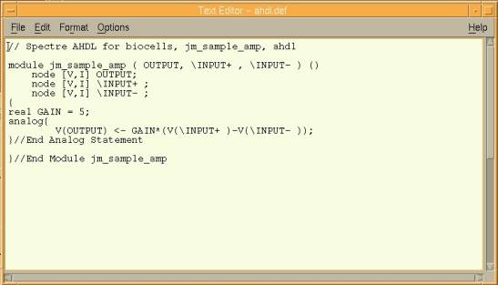
- Fix all “special” identifiers by making them escaped identifiers. That is, precede the identifiers with a backslash (\) and follow them with a blank space. Your code should now look like the code in the figure below.
- Add the following code between the curly brackets.
real
GAIN = 5;
analog{
V(OUTPUT) <- GAIN*(V(\INPUT+
)-V(\INPUT- ));
}//End Analog Statement
Your code should now look like this:
There are several things to note here:
i.
The double-slash (//) indicates a comment. Comments continue until the end of the line.
ii.
Variables can be declared as either real (shown) or integer. Variable declaration occurs outside the
“analog” statement but inside the module “body” (inside the original curly
brackets).
iii.
Variable assignment uses an equal sign (=).
iv.
Node assignment uses an assignment operator (<-).
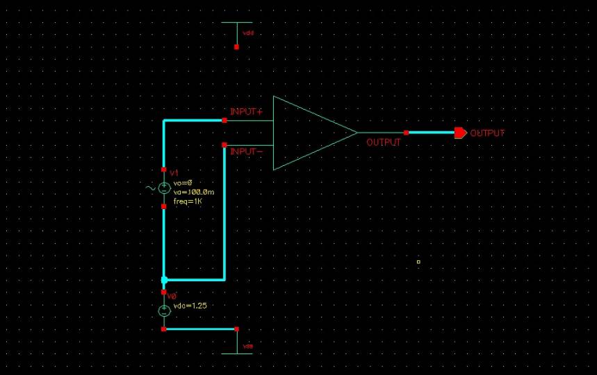
- Create a schematic file as shown in the figure below. Use the following assignments:
i. vdd = 2.5 Volts
ii. vss = 0 Volts
iii. ac source: offset voltage = 0 Volts
iv. ac source: 100 mVolts
v. ac source: frequency = 1 kHz
vi. dc source: dc voltage = 1.7 Volts
- Perform a transient analysis of the circuit. Choose a stop time of 2 mS.
- Plot the resulting voltages. The plot should look like the plot in the figure below.

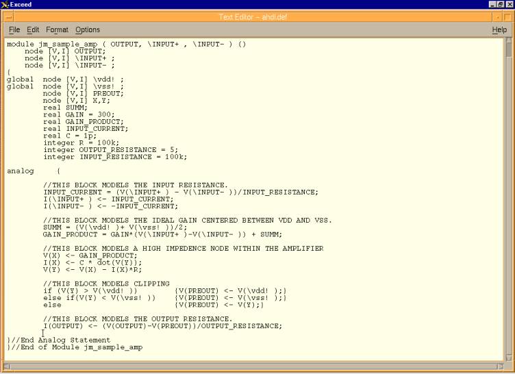
The model that we just created isn’t very good. It doesn’t take into account input or output
resistances, high frequency rolloff, distortion effects such as clipping, input
offset voltage, etc. Also notice how
the output oscillates about 0 Volts despite our voltage rails being set at 0
and 2.5 Volts.
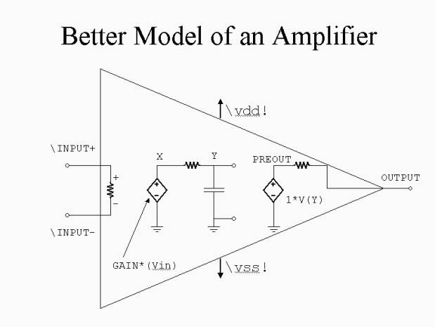
You have now completed the tutorial “Getting Started with AHDL”. See below for an example that better models an actual amplifier. The block diagram that represents the code is shown below.