Modulation
Communication and channels
We will now discuss how information is actually communicated
A communication channel is a physical medium or logical construct that allows transmission of information
- A twisted pair of wires
- Fiber-optic cable
- Radio signals over the air
- The radio frequency range between 900 kHz and 910 kHz
- An HDMI cable
Not every signal can be readily transmitted on every channel; it needs to be modulated first
Modulation, informally, is the act of fitting a signal into a channel.
But first let’s see how operations involving signals affect the spectrum. This will be central to our discussion of modulation
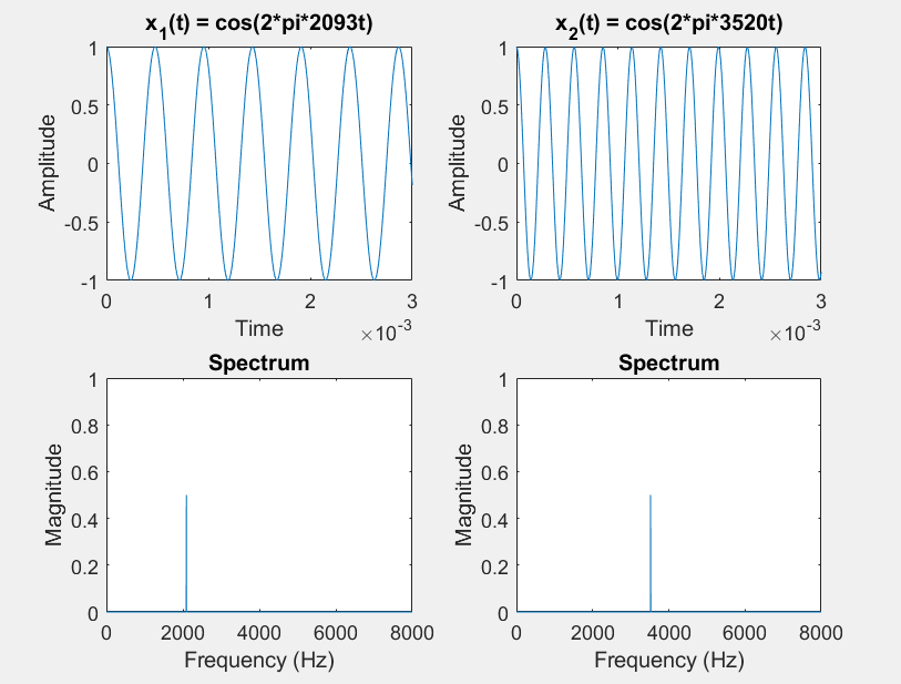
Case study on sinusoids
Consider two sinusoids:
$x_{1}\left( t \right) = \cos\left( 2\pi 2093t \right) = C$ $x_{2}\left( t \right) = \cos\left( 2\pi 3520t \right) = A$ octave up
Listen to them (sampled at 44100 hertz)
If we add them $x_{sum}\left( t \right) = x_{1}\left( t \right) + x_{2}(t) = \cos{\left( 2\pi 2093t \right) +}\cos\left( 2\pi 3520t \right)$
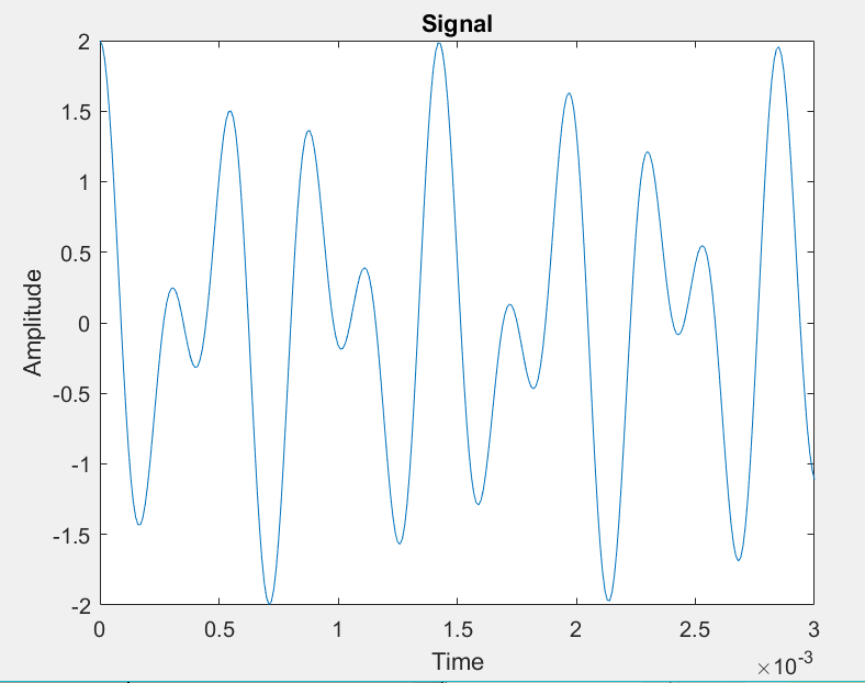
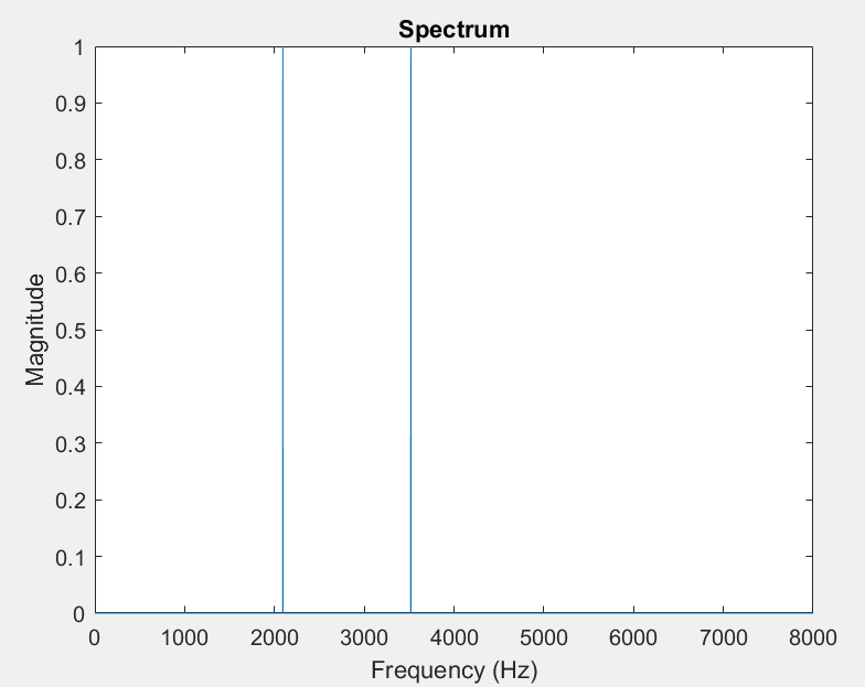
The spectrum is just the sum of the spectra: Superposition.
If we multiply them $x_{product}\left( t \right) = x_{1}\left( t \right)x_{2}(t) = \cos\left( 2\pi 2093t \right)\cos\left( 2\pi 3520t \right)$
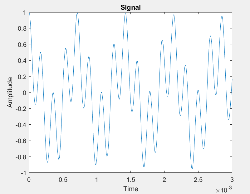
How did we get frequencies that did not exist in either of the signals?
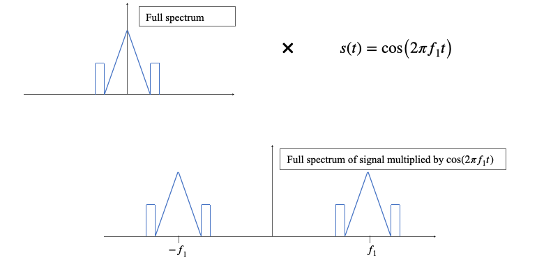
What happens if we multiply a given signal by a cosine?
Given that any signal is a weighted sum (integral) of complex exponentials, let’s see what happens to a complex exponential at frequency $f$
$x\left( t \right) = e^{i2\pi ft}$
$y\left( t \right) = x\left( t \right)\cos{(2\pi f_{1}t)} = e^{i2\pi ft}\frac{e^{i2\pi f_{1}t} + e^{- i2\pi f_{1}t}}{2} = \frac{1}{2}e^{i2\pi\left( f + f_{1} \right)t} + \frac{1}{2}e^{i2\pi\left( f - f_{1} \right)t}$
We get two frequencies, $f + f_{1}$ and $f - f_{1}$ Visually
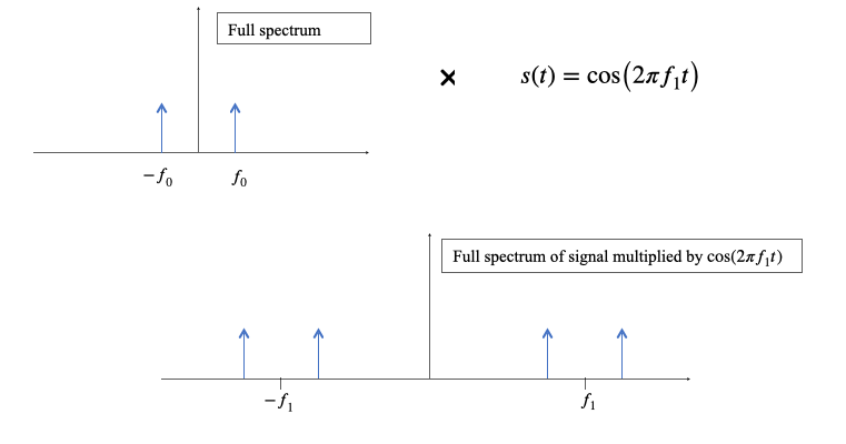
We can also see what happens when we multiply two cosines with trig identities, although this doesn’t tell us how a general signal is affected by the multiplication
Trig identity: $\cos\left( a \right)\cos\left( b \right) = \frac{1}{2}(\cos\left( a + b \right) + \cos\left( a - b \right))$
So, multiplication of two cosines produces sum and difference frequencies.
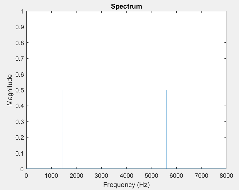
In the example we just looked at $f_{1} + f_{2} = 2093 + 3520 = 5613Hz$, $f_{1} - f_{2} = 1427Hz$
$x_{product}\left( t \right) = x_{1}\left( t \right)x_{2}\left( t \right) = \cos\left( 2\pi 2093t \right)\cos\left( 2\pi 3520t \right)$
$= \frac{1}{2}\left( \cos{\left( 2\pi\left( 3520 - 2093 \right)t \right) + \cos\left( 2\pi\left( 3520 + 2093 \right)t \right)} \right)$
$= \frac{1}{2}\left( \cos{\left( 2\pi 1427t \right) + \cos\left( 2\pi 5613t \right)} \right)$
To be able to transmit information over a channel, we typically need to modulate the signal
Why modulation?
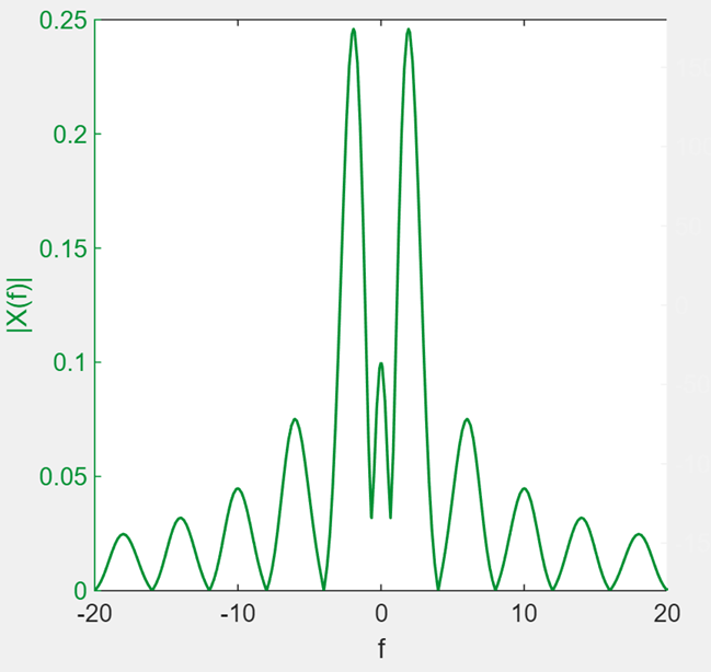
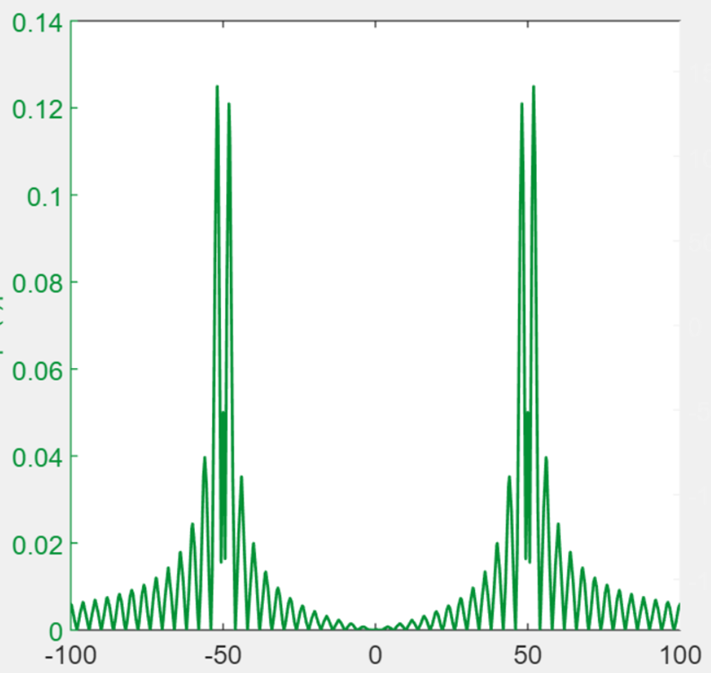
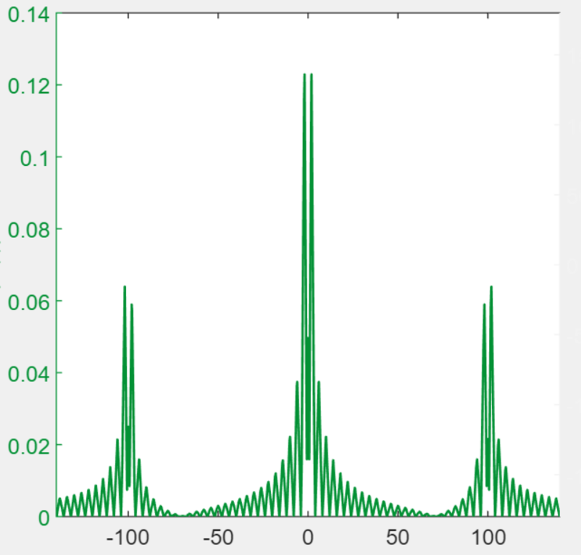
Commonly, the signal frequency range (signal bandwidth) does not line up with the frequency range the channel can carry (channel bandwidth or channel passband). For instance, consider the spectrum of an audio signal generated by recording a mandolin:
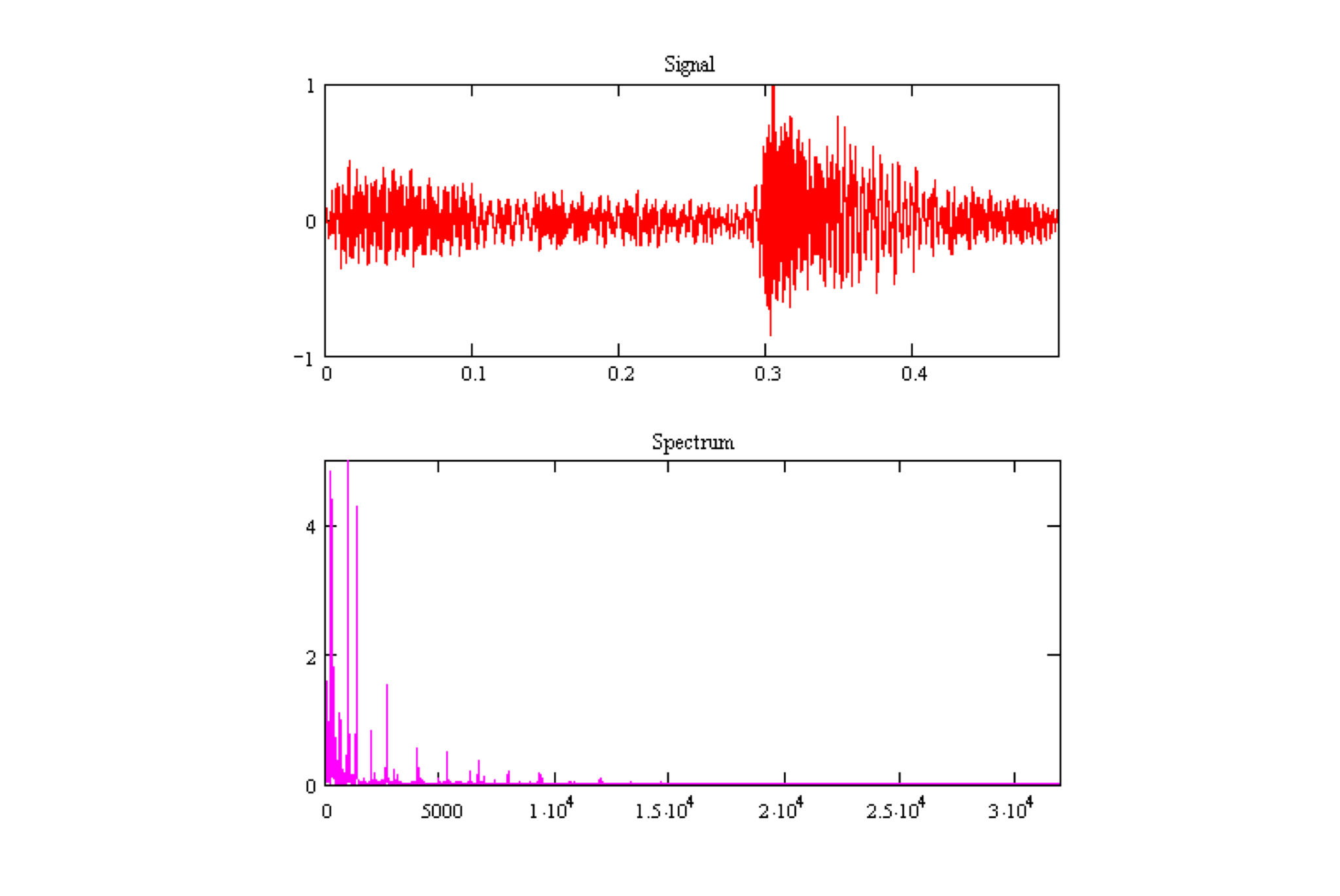
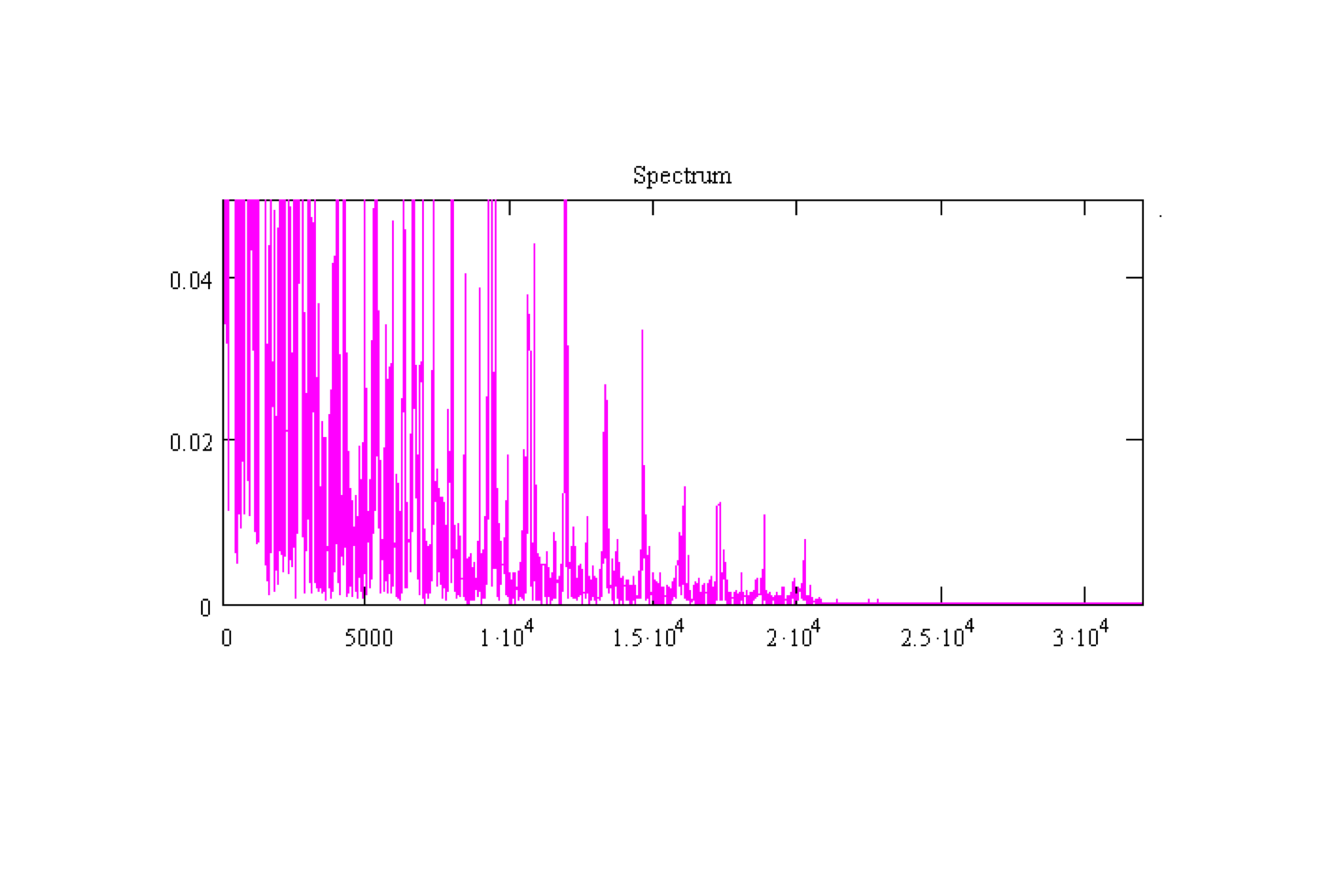
Zooming in, this signal appears to have a 20 kHz bandwidth. We have two options:
- We could transmit that signal as is (baseband transmission).
- Transform the information so that it is transmitted in a different frequency range (modulated transmission).
Baseband versus modulation
Baseband transmission has many disadvantages:
Disregards the characteristics of the channel at those frequencies. Other frequency ranges may have better signal-to-noise ratio or less attenuation (signal loss).
Prevents others from reusing that bandwidth without some kind of orthogonal coding.
Does not make use of the full available spectrum.
These are overcome by modulation:
Transmitted frequency range can fit the channel characteristics for optimal gain, SNR.
Other transmissions can use different frequency ranges, avoiding congestion or interference.
Make use of all available spectrum by spreading different signals throughout.
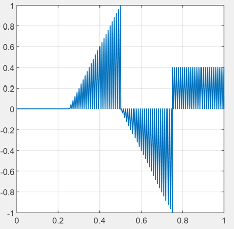
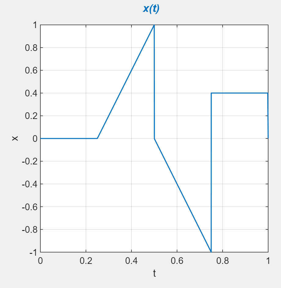
Modulation is important for digital signals because unmodulated digital signals have sharp changes resulting in high bandwidth requirement if transmitted in baseband
Diving into Modulation
Modulation typically involves two signals: Carrier: a waveform chosen to fit the channel well Message signal or modulation signal: the signal representing information to be transmitting
Modulation can be considered the systematic alteration of the carrier by the message.
- Amplitude modulation: change the amplitude of the carrier based on the message
- Frequency modulation
- Phase modulation
Amplitude modulation
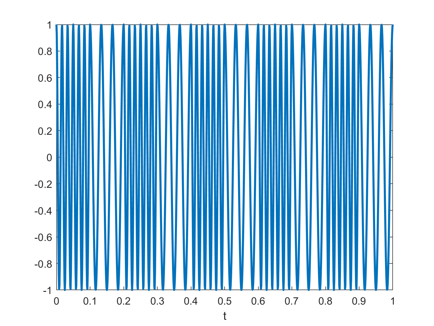
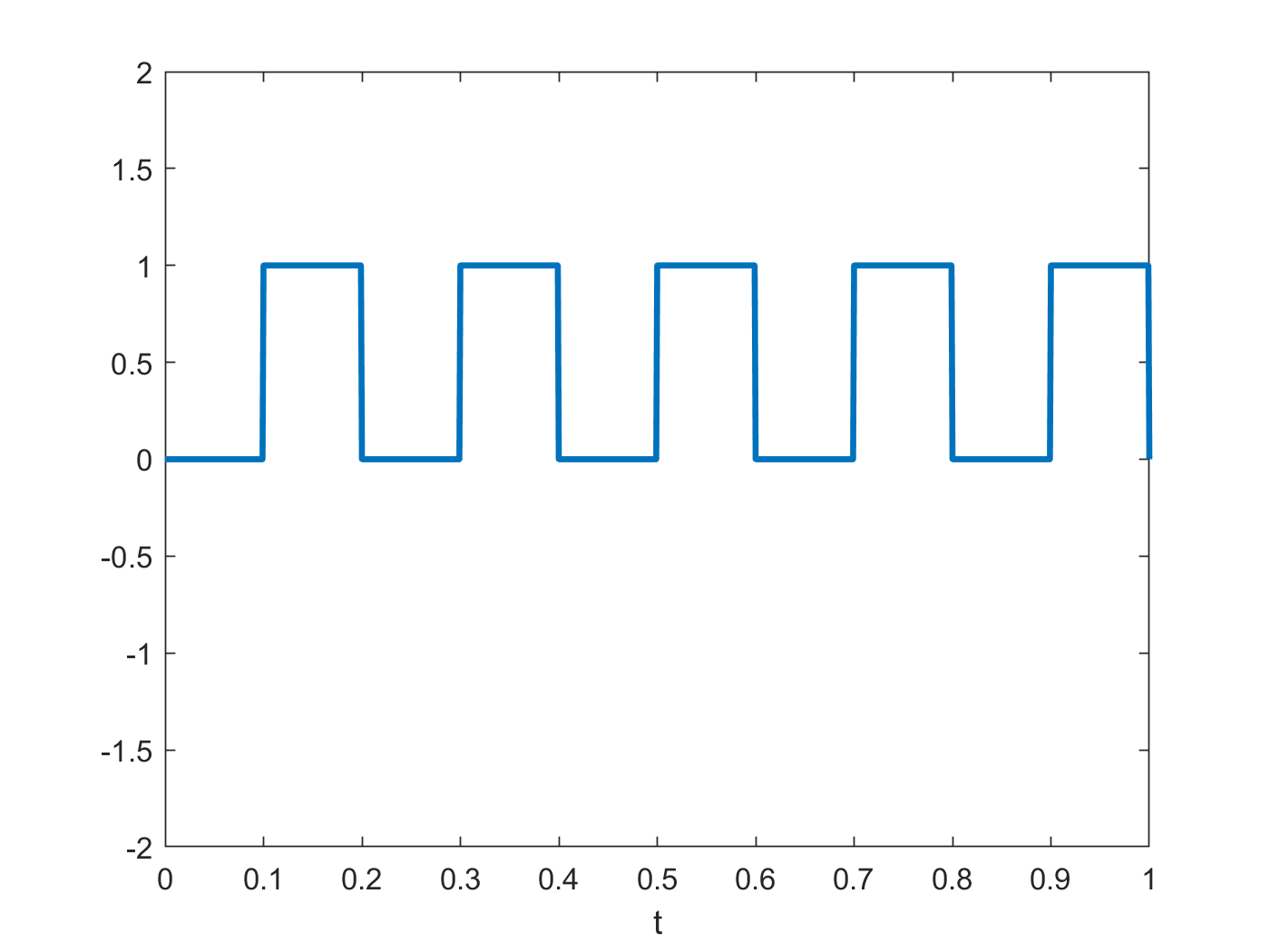
Consider a carrier signal $x_{c}(t)$ and a message signal, $x_{m}\left( t \right)$
x
=
Amplitude Modulation:the frequency domain
x
=
An advantage of modulation is that it allows us to send multiple signals over the same medium at different frequencies. At the receiver, these signals can be separated by using a frequency-selective filter at a given frequency and with an appropriate bandwidth.
AM radio
Older radio stations frequently used amplitude modulation to transmit audio on high frequency carriers licensed to them for broadcasting by the FCC. Many of these AM radio stations still use such modulation (although many broadcast digital (HD) versions on top of it).
The FCC has allocated ~10 kHz to each AM radio station, which permits stations to broadcast without interfering with each other.
A broadcast signal is first recorded and filtered at a frequency < 5 kHz (why?), then modulated to the assigned carrier frequency, and amplified and transmitted.
The AM tuner or receiver needs to isolate and demodulate the desired signal. This can be done in two ways:
Synchronous demodulation: we first multiply by the carrier the received signal and then apply a low-pass filter.
Envelope detection: A simpler method that does not need the carrier. The modulation is slightly different, and demodulation is performed via a bandpass filter and finding the envelop of the signal. This type of AM demodulation is easier, hence its prevalence in the early days of radio.
Synchronous
demodulation This is close, but not exactly the message signal:


We see that there are high frequency components that cause the high frequency oscillation. To get rid of these, we can simply pass the signal through a low pass filter.
Synchronous demodulation
Overall the message signal $x_{m}\left( t \right)$ is multiplied by $\cos{(2\pi f_{c}t)}$ twice, once during modulation and once during demodulation. So it is multiplied by $\cos\left( 2\pi f_{c}t \right)^{2}.$
Let’s see what this does to a signal:
$\cos{\left( \alpha \right)\cos{\left( \beta \right) = \frac{1}{2}\left( \cos\left( \alpha + \beta \right) + \cos\left( \alpha - \beta \right) \right)}}$
So
$\cos\left( 2\pi f_{c}t \right)^{2} = \frac{1}{2} + \frac{1}{2}\cos{(2\pi 2f_{c}t)}$
$x_{AM}(t)\cos\left( 2\pi f_{c}t \right)^{2} = \frac{1}{2}x_{AM}(t) + \frac{1}{2}\cos{(2\pi 2f_{c}t)}x_{AM}(t)$
$\cos{(2\pi 2f_{c}t)}x_{AM}(t)$ is eliminated using a low-pass filter.
AM demodulation
Synchronous demodulation requires an exact replica carrier signal, without any time offset or frequency shift (hence, synchronous)
This can be difficult in practice
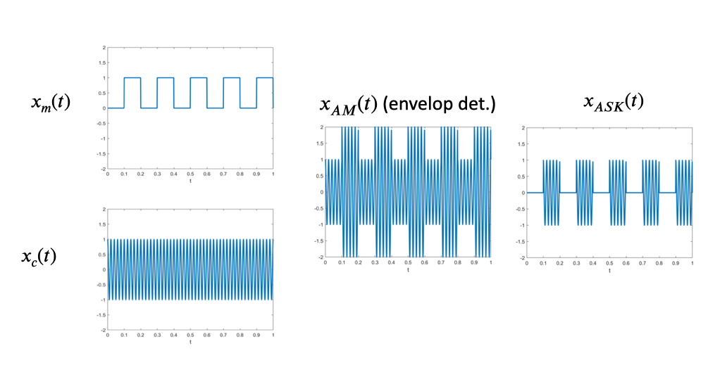
Let’s compare the message and the AM signals:
When the message is positive, message signal matches the envelop.
What if we shift the message signal so that it becomes positive?
Demodulation = envelope detection
Observe the shape of the original data (modulation) signal on top of the sinusoid:
Approach: find peaks of AM signal, interpolate between them, and subtract offset and rescale.
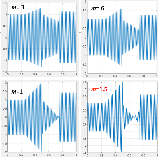
The modulation index
More generally,
$xAM\left( t \right) = x_{c}\left( t \right)\left\lbrack 1 + mx_{m}\left( t \right) \right\rbrack$ where $m$ is the modulation index, $0 < m \leq 1$.
What happens as m increases from 0 to 1?
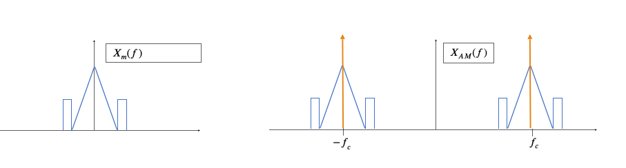
What happens in the frequency domain?
$x_{AM}\left( t \right) = \cos\left( 2\pi f_{c}t \right)\left( 1 + mx_{m}\left( t \right) \right) = \cos{\left( 2\pi f_{c}t \right) +}m\cos\left( 2\pi f_{c}t \right)x_{m}\left( t \right)$
The Fourier transform of $x_{AM}\left( t \right)$, i.e., $X_{AM}(f)$ consist of the Fourier transform of $\cos\left( 2\pi f_{c}t \right)$ plus shifted versions of the Fourier transform of $x_{m}\left( t \right).$
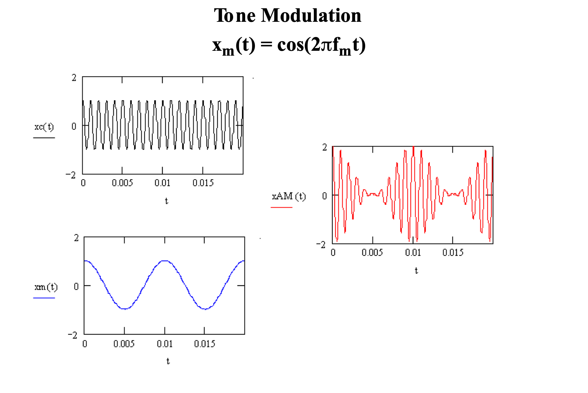
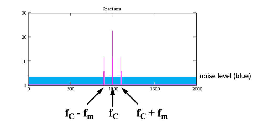
Example: AM modulation of a tone
To understand what’s happening in the frequency domain, it’s useful to imagine modulating a simple tone:
$x_{m}\left( t \right) = \cos\left( 2\pi f_{m}t \right)$
Then, we can use trigonometry to find the sinusoidal components of $x_{AM}(t)$.
Significance: the information in $x_{m}(t)$ has been shifted in frequency from f~m~ to f~C~+f~m~ and f~C~-f~m~.
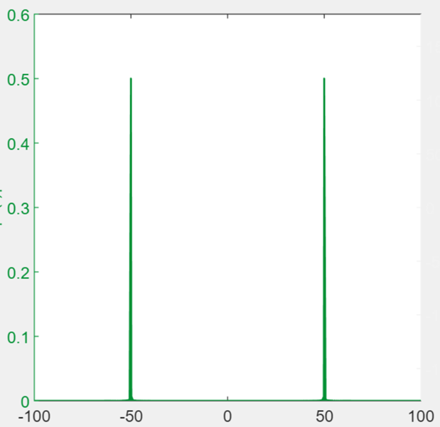
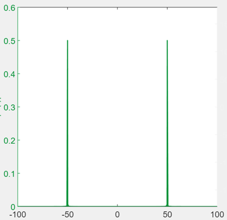
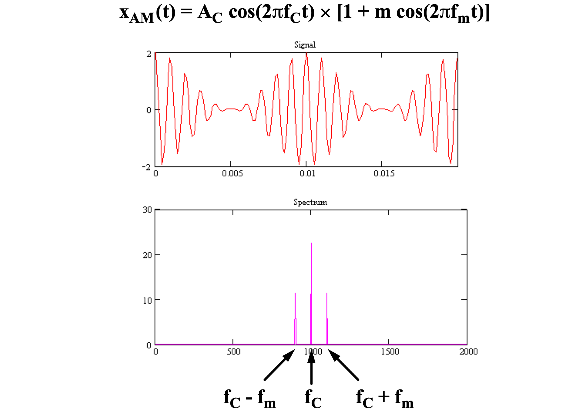
AM modulation of a tone: spectrum
So, given a suitable carrier frequency (f~C~ > f~m~), the positive spectrum of xAM(t) looks like this:
The version of AM where $x_{AM}\left( t \right) = \cos{(2\pi f_{c}t)(1 + mx_{m}\left( t \right))}$ is usually simply referred to as AM.
The version in which $x_{AM}\left( t \right) = \cos{(2\pi f_{c}t)}x_{m}\left( t \right)$ is referred to as AM-suppressed carrier (AM-SC), as the carrier is not added to the signal anymore. AM-SC has lower transmitted power.
AM-SC can be demodulated by the synchronous detection approach (multiplying by the carrier cosine).
AM-SC cannot be demodulated by envelope detection.
Since there are two copies of the message spectrum in the AM signal, we’ll get one copy on the left side of 0-frequency (DC) and one copy on the right side. These are called the lower side band (LSB) and upper side band (USB). All the signal information is in both the LSB and USB.
Why not just transmit and receive one of these, saving half the bandwidth? (assumes real-valued signal)
Answer: You can, it’s called single side band (SSB) transmission (used in shortwave, TV, etc.) But, you’ll need a more sophisticated receiver to demodulate.
Digital amplitude modulation
When transmitting digital signals (binary), the demodulated signal can only be two values. Thus, a simpler model can be used to modulate or transmit: just multiply the carrier by 0/1.
This is called amplitude shift keying (ASK). Note how it compares to AM of a binary signal:
Limitations of AM
Carrier power – significant, but does not convey information
Can use AM-SC with suppressed carrier, but envelope detection no longer possible
Maximum scaling – message signal must be scaled to fit carrier to permit envelope detection
Recall: when mx~m~(t) < -1, the envelope crosses itself
Redundant frequency content
Single-sideband AM possible, but requires more complicated demodulation
Susceptibility to noise
Consider the effect of noise on an AM signal:
What happens where 1+mx~m~(t) is large?
What about when 1+mx~m~(t) is close to zero?
What about an interfering signal?
What happens with noise or interference in the frequency domain?
Revisiting the carrier signal
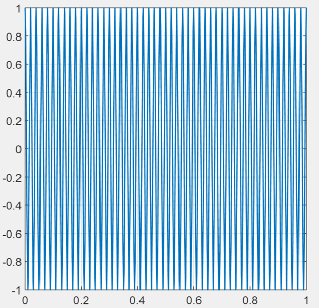
Let us revisit the definition of a sinusoidal carrier signal x~C~(t):
$x_{C}\left( t \right) = A\cos\left( 2\pi f_{C}t + \phi \right)$
So far, we considered amplitude modulation, where A becomes a function of the message x~m~(t):
$A = 1 + mx_{m}\left( t \right)$
However, we are not limited to modifying the amplitude A. We can also modify the frequency of the carrier and its phase:
Frequency becomes a function of the message signal versus time
Phase becomes a function of the message signal
Consider: frequency is the time derivative of the argument of the sinusoid
Frequency modulation
The argument θ in the sinusoidal carrier is a function of time:
$\theta\left( t \right) = 2\pi f_{C}t + \phi$
Then the derivative of θ with respect to t is the carrier frequency:
$\frac{d\theta\left( t \right)}{dt} = 2\pi f_{C}$
Instead, let this be a function of the message signal as well:
$\frac{d\theta\left( t \right)}{dt} = 2\pi\left( f_{C} + f_{\Delta}x_{m}\left( t \right) \right)$
Let f~Δ~ be a scaling factor for FM, like m for AM (this will turn out to be a function of available bandwidth)Then, the argument becomes an integral (time t=0 is the beginning of the transmission):
$\theta\left( t \right) = 2\pi\left( f_{C}t + f_{\Delta}\int_{0}^{t}{x_{m}\left( \tau \right)d\tau} \right) + \phi$
The amplitude of the carrier remains constant
Consistent noise scaling
The frequency affects how rapidly the sinusoid changes sign: higher frequency, more sign changes per unit time.
Demodulation: track sign change rate
More complicated than amplitude demodulation (envelope detection), but less noise sensitivity since signal is “always on”
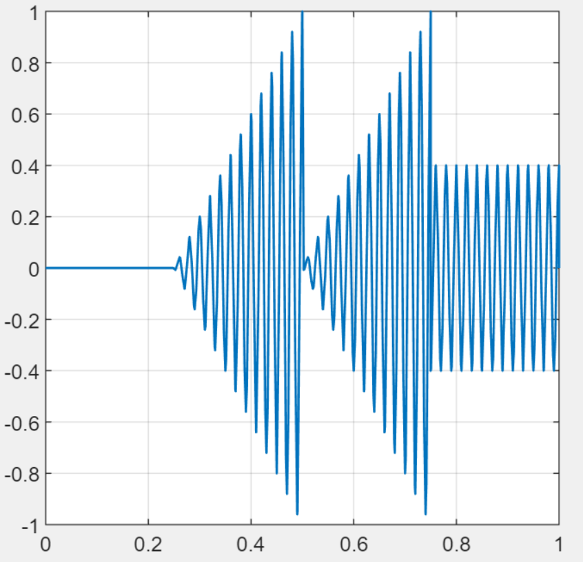
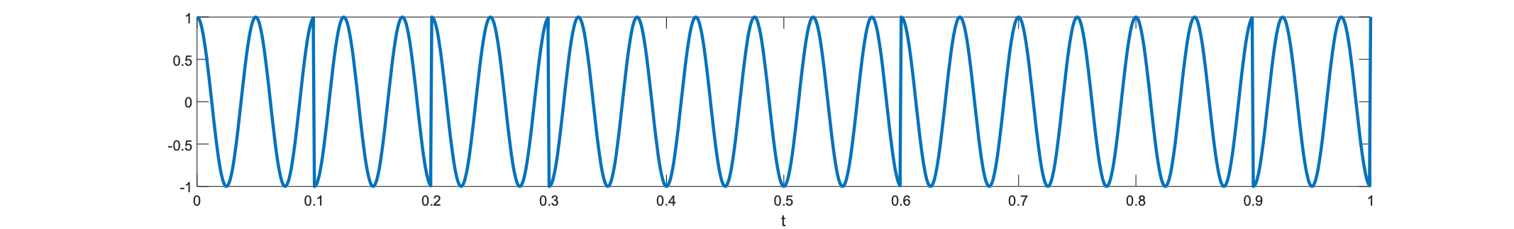
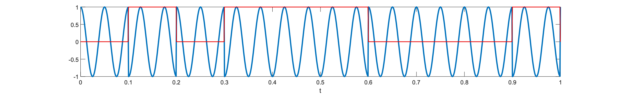
Analog frequency modulation (FM) digital frequency shift keying (FSK)
Two fixed frequencies: f~0~ for “0”, f~1~ for “1”
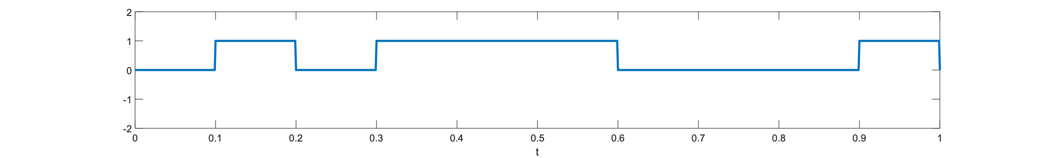
Consider a simple binary message x~m~(t):
Phase modulation
Frequency is not the only choice in the argument of the sinusoid for modulation. Also consider modulating the phase φ:
$\theta\left( t \right) = 2\pi f_{C}t + \phi$
Replace phase with a message signal x~m~(t):
$\theta\left( t \right) = 2\pi f_{C}t + x_{m}\left( t \right) + \phi$
The message signal can be scaled by a constant factor as well.
What if we take the derivative? Phase modulation becomes a special case of FM:
$\frac{d\theta\left( t \right)}{dt} = 2\pi\left( f_{C} + \frac{dx_{m}\left( t \right)}{dt} \right)$
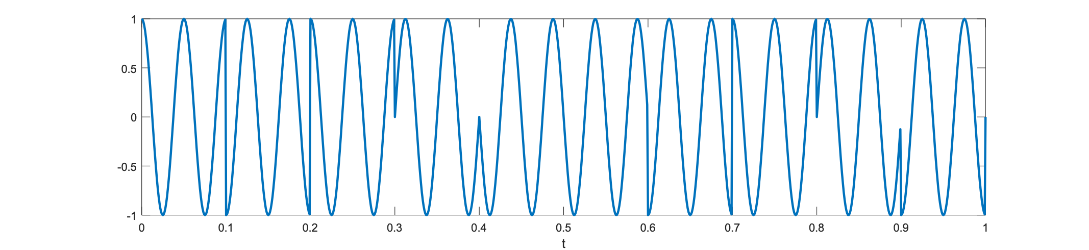
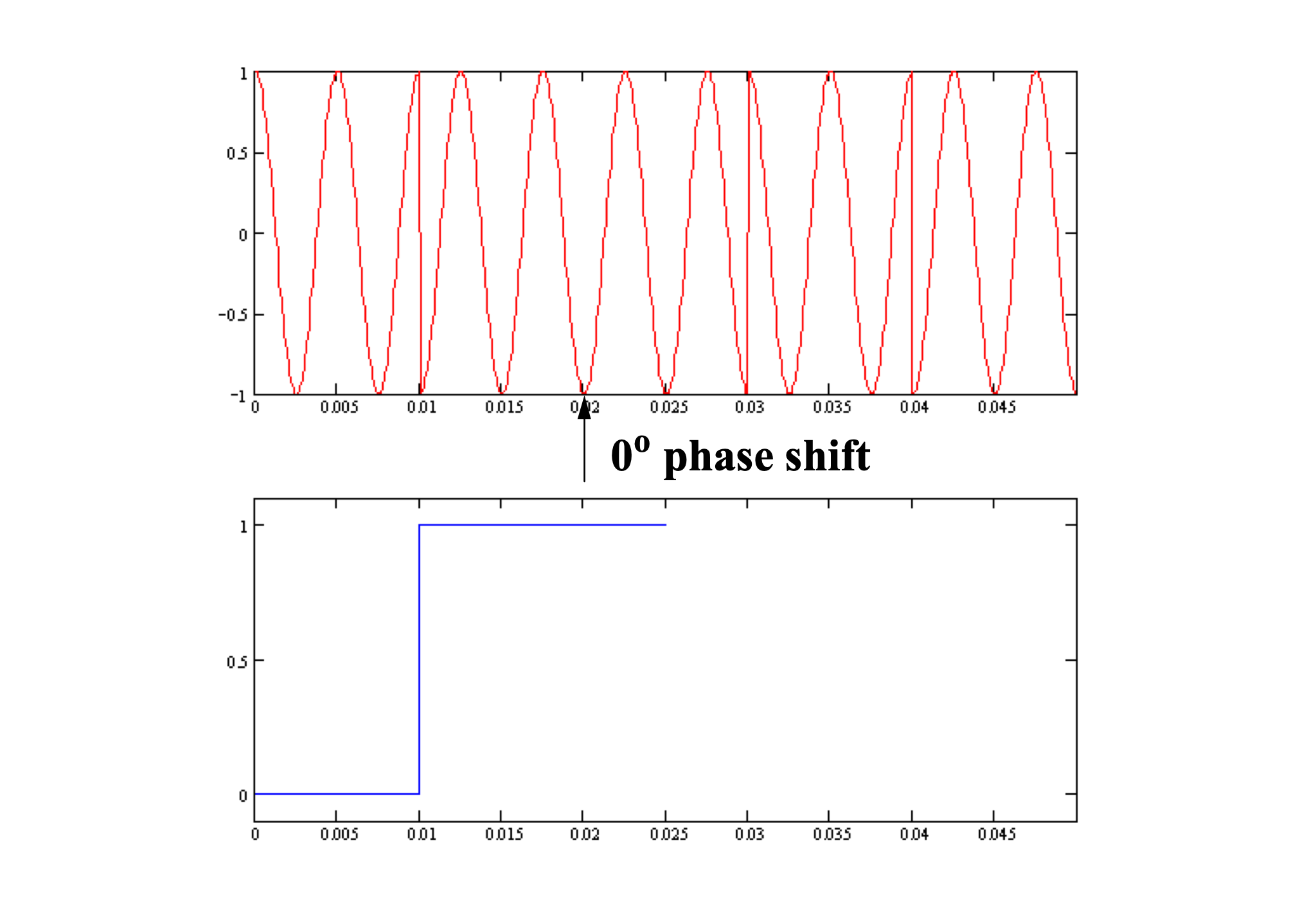
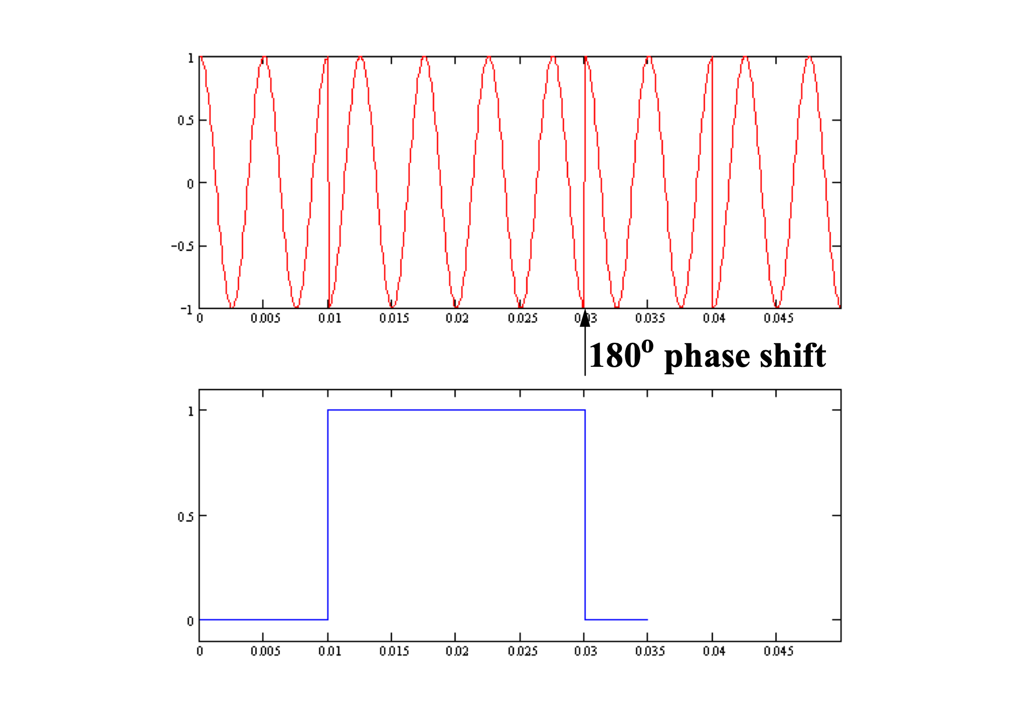
Analog phase modulation digital phase shift keying (PSK)
Replace analog xm(t) with binary “0” and “1”, so phase jumps between φ~0~ (usually 0) and φ~1~ (usually 180 degrees). Unlike FSK the signal is not differentiable.
Let’s take a closer look: $0 \rightarrow phase = 0,1 \rightarrow phase = 180$
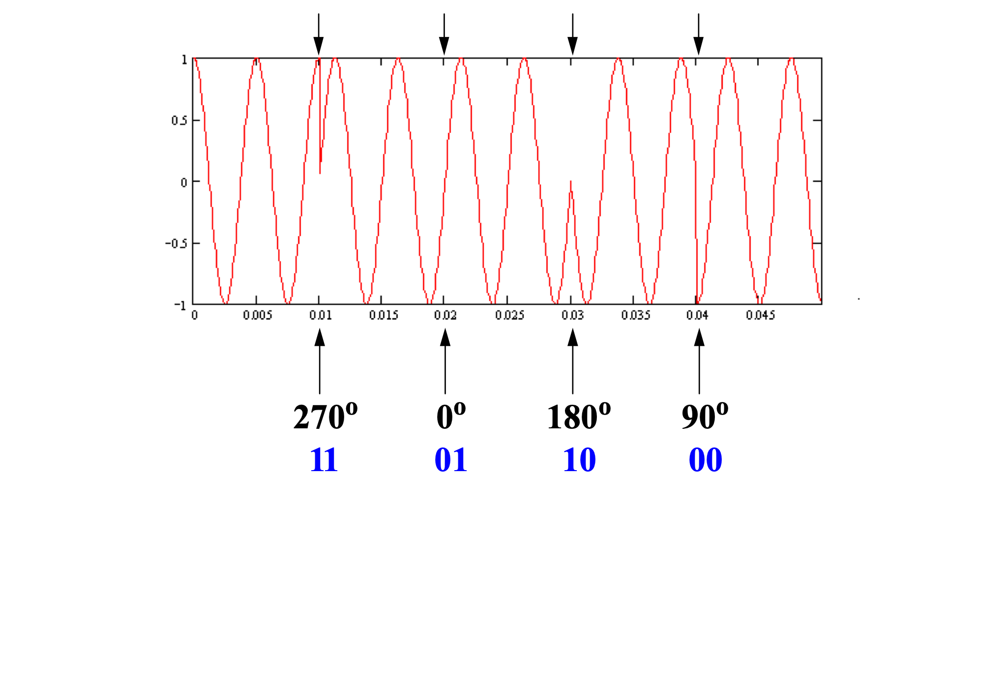
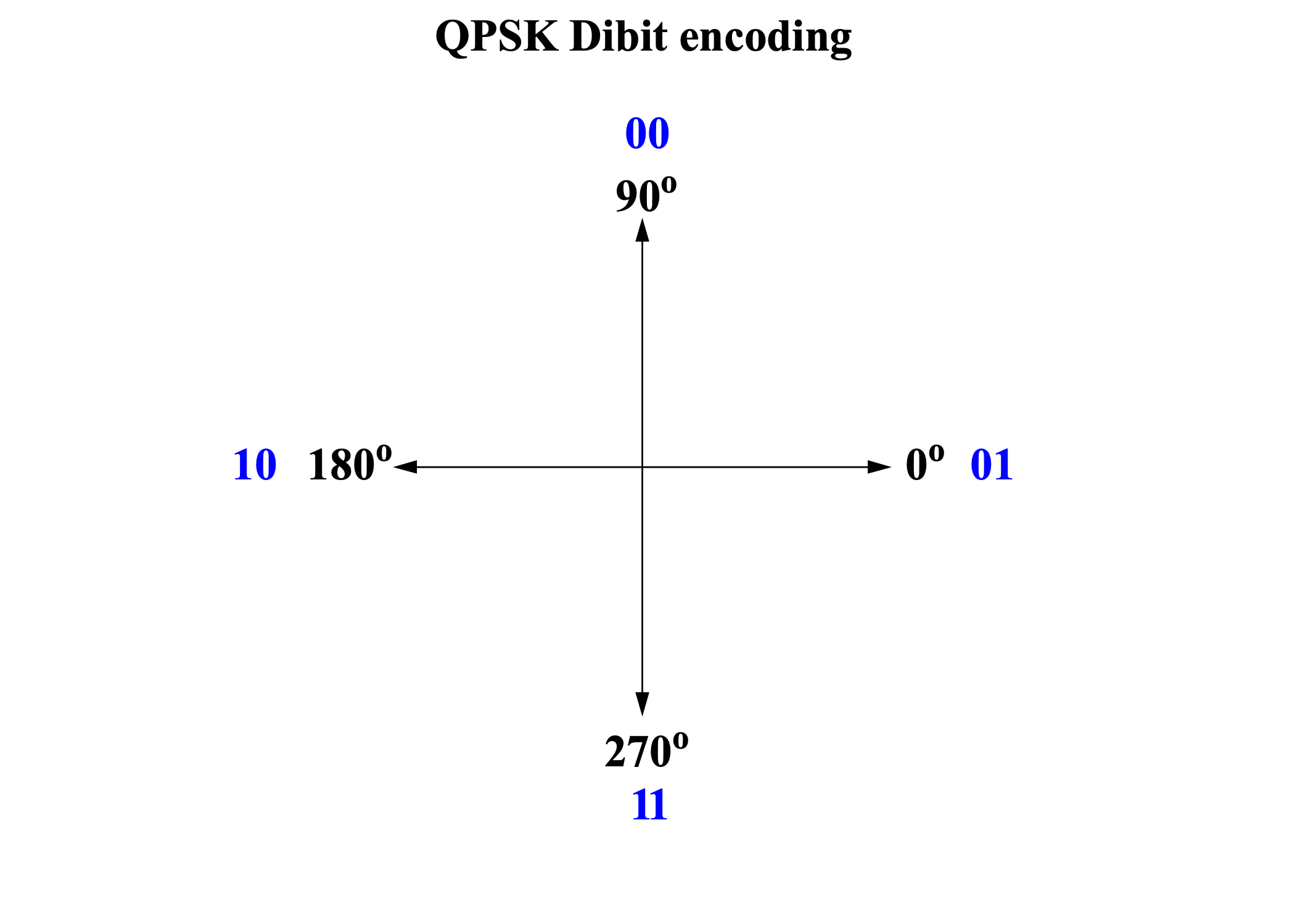
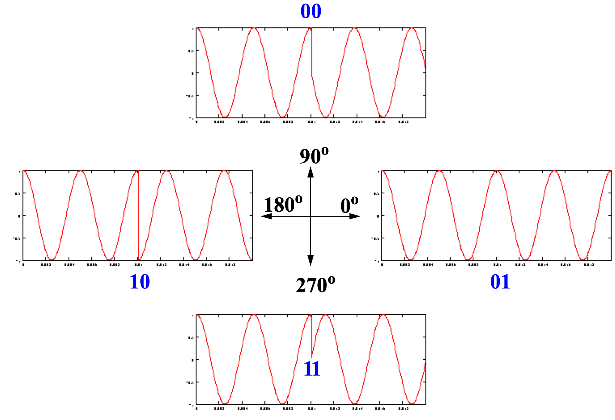
Quadratic phase shift keying
Can we send more than 1 bit in each interval?
Yes: $\left{ \begin{matrix}
00:phase = 0
01:phase = 90
10:phase = 180
11:phase = 270
\end{matrix} \right.\ $
Differential phase shift keying (DPSK)
Alternatively, we can set $0 \rightarrow phasestaysthesame,1 \rightarrow phasejumpsby180$
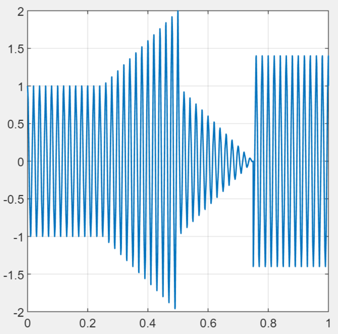
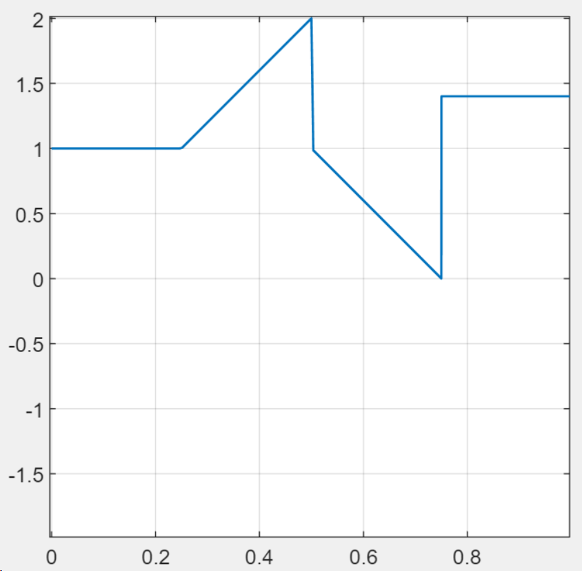
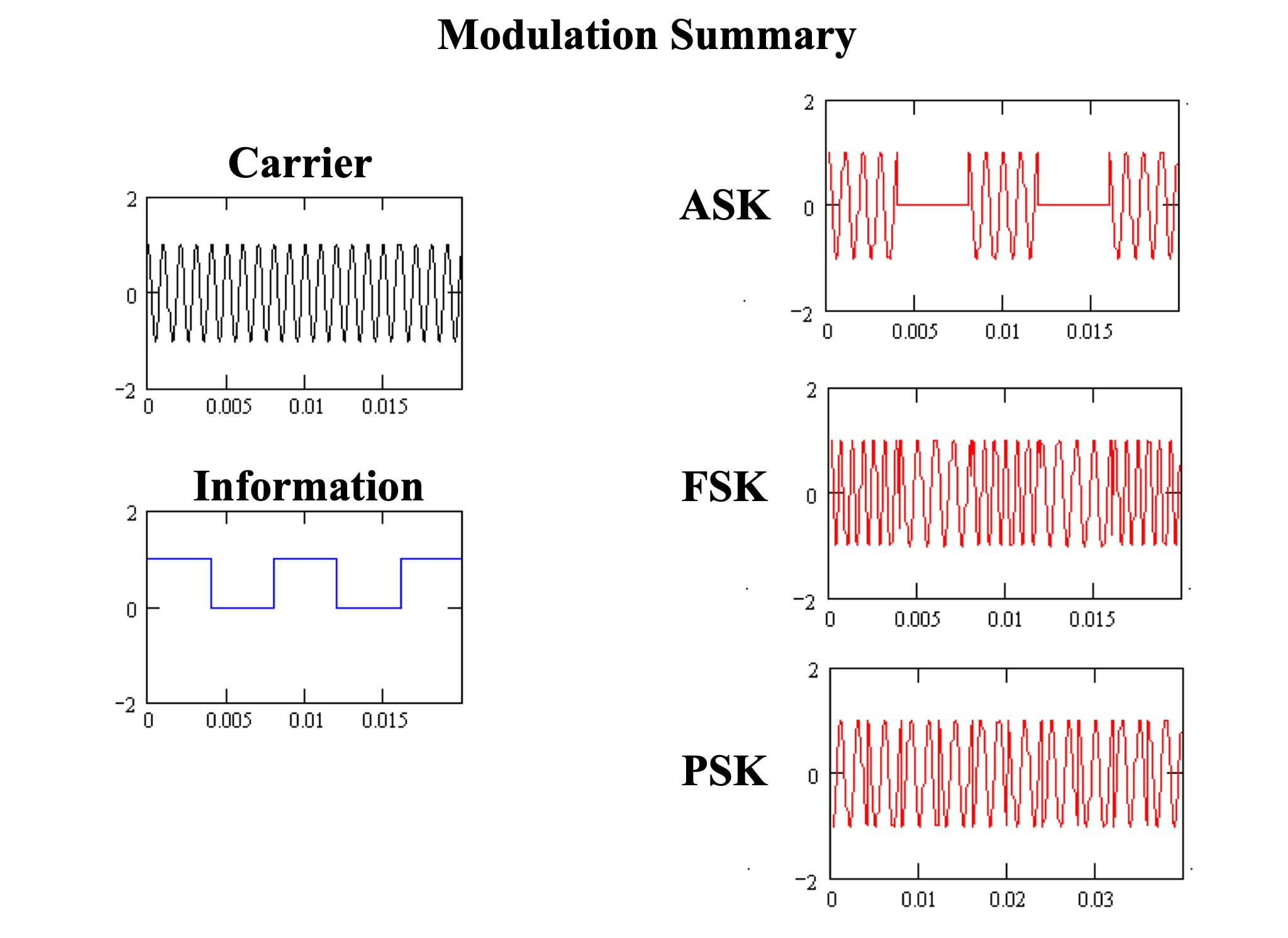
Modulation summary
Three methods for modulating binary/digital signals:
Amplitude shift keying: track amplitude zero/one
Frequency shift keying: track zero-crossing rate
Phase shift keying: track phase jumps/discontinuities
Advantages and disadvantages
Amplitude modulation (AM/ASK):
Simple design, demodulation (e.g., envelope detection)
Susceptible to noise (especially when transmitting small/zero values)
Frequency modulation (FM/FSK):
Amplitude constant, so signal always present and better noise immunity
Need to track zero-crossing rate, not just instantaneous amplitude
Frequencies spread out, requiring more bandwidth
Phase modulation (PSK):
Similar advantages to FM/FSK, but no frequency spreading!
Modern cellular modems
Cellular modems transmit/receive voice/data from phone over cellular network
Responsible for encoding and modulating signal according to network type
Early modems: mainly amplitude modulation (ASK)
Modern modems: combination of PSK, ASK (can encode information in amplitude and phase changes simultaneously; harder to encode in both FSK and PSK)
Modern modems actually go beyond PSK to multibit encoding
Let’s investigate phase modulation a bit more carefully…
5G modem will require its own chip for now; current 4G LTE use integrated “system-on-chip” solutions
Phase shift keying: decoding
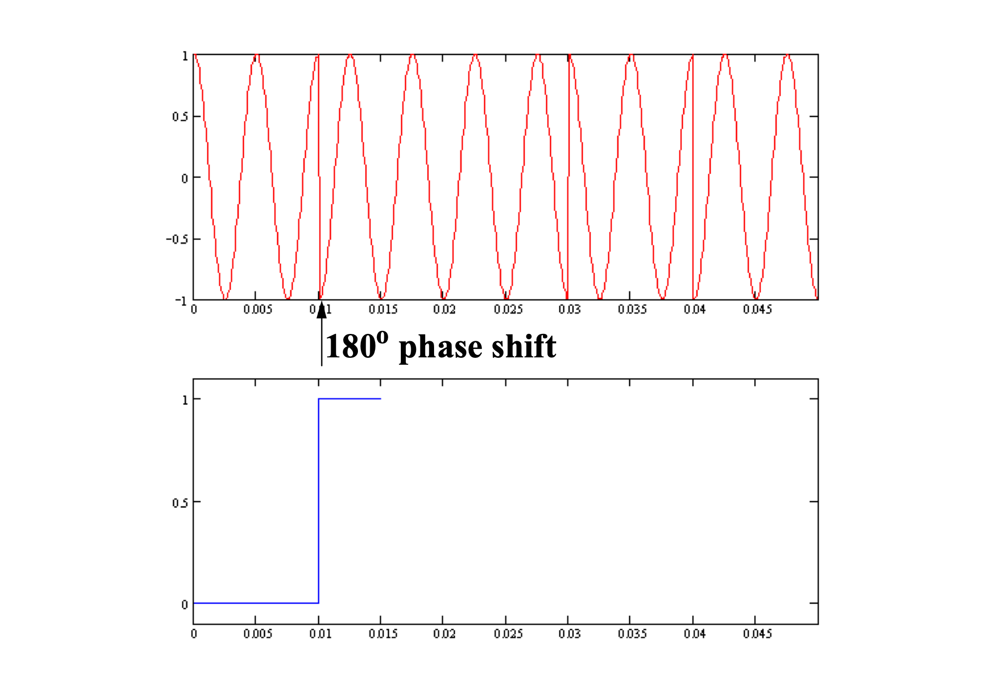
180 degree phase shift (a “1”) introduces a jump discontinuity in the carrier:
But a “0” doesn’t create any shift.
Transmitter, receiver need to agree on a bit rate.
Instead of encoding “0” and “1” directly, we use differential encoding:
A change is a “1”, no change is a “0”
Requires we know how it starts
If we miss a bit, we’re in trouble…
With differential coding, another “1” indicates a change from 1 0:
Can we do better?
180 degree jumps are big, easy to detect
90 degree jumps go between ±1 and 0, also relatively easy to detect
Let’s allow 90, 180, 270 degree jumps: quadrature phase shift keying (QPSK)
Quadrature phase shift keying
Define a “dibit” (two bit message) to encode as 0, 90, 180, 270 degree phase shifts:
These dibit assignments to each phase jump are arbitrary…
A little more complicated, but twice the information transfer!
What is the bit rate for this example?
= (2 bits) / (0.01 seconds) = 200 bits/sec
Regular encoding:
11011000
Differential encoding (1 = change, 0 = no change):
10010000
Your turn
Sketch carrier modulated using QPSK for binary signal “10010011” using regular (not differential) encoding, assuming each dibit is modulated over a full period of x~C~(t)